


Quality and Measurement of Crossover Components
A crossover is a passive filter network that directs the appropriate frequencies to the woofer, midrange driver, and tweeter. The entire audio signal comes from a single amplifier output, and the crossover’s job is to ensure that each speaker receives only the frequency range for which it was designed.
This is one of the most critical aspects of a speaker system, both in terms of sound quality and technical performance. A poorly designed crossover or one built with low-quality components will degrade even the best speakers to mediocrity. Conversely, a precisely tuned crossover built with high-quality components brings out the true potential of the speakers.
The Basic Structure of a Crossover
Filter Orders and Slope
A crossover consists of low-pass, band-pass, and high-pass filters. The slope of each filter depends on its order:
- 1st-order filter: −6 dB/octave slope. Simple and time-coherent, but places a heavy load on the speakers in the transition band.
- 2nd-order filter: −12 dB/octave. The most common—a good compromise between slope and complexity.
- 3rd-order filter: −18 dB/octave. Better separation, but the phase response becomes more complex.
- 4th-order filter: −24 dB/octave. With Linkwitz–Riley alignment, it provides ideal phase characteristics.
The filter order does not just determine the slope—it also determines the number of components. A second-order filter requires one capacitor and one inductor on each side (low-pass and high-pass). In a five-way crossover, that’s already eight to ten reactive components, each of which affects the final result.
The most common crossover topologies
Butterworth (maximum amplitude flatness): There is no peak in the transition band, and the frequency response is as flat as possible. However, the phase response is not zero—this affects time coherence.
Linkwitz–Riley (−6 dB at the crossover frequency): The two filter branches are typically set to −6 dB per branch at the crossover point (in a 4th-order LR filter, this aligns with the overall response of the cascaded 2+2nd-order filters). For in-phase summation, the two speakers must also be acoustically in phase around the crossover point—in the case of a passive LR2, the two branches are 180° out of phase with each other at the crossover point, so in practice, the tweeter (or the high-frequency branch) is connected with reversed polarity to ensure that the sum of the radiated sound remains correct; without this, the low and high frequencies would cancel each other out in the crossover band. When used in pairs with proper crossover settings, second-order filters provide a fourth-order LR solution—this is the most common professional choice.
Bessel (characteristic that strives for maximally uniform group delay): Good impulse response, but the transition band is less steep. Less common in passive crossovers than Butterworth or LR; more frequently chosen in active/DSP systems where uniform group delay is a priority.
The capacitor—the most sensitive component
The crossover capacitor is the backbone of electrical filtering. In the high-pass branch, a series capacitor protects the tweeter from low frequencies; in the low-pass branch, a parallel capacitor reduces the flow of high frequencies into the woofer.
Capacitor Types and Their Applications
Film capacitors (polypropylene, polyester):
In the high-pass filters of the high- and mid-frequency branches (small to medium µF), film capacitors (MKP, PPS, etc.) are the preferred choice: they are stable, have low nonlinearity, and exhibit good high-frequency performance.
For high-capacitance (typically ~100–470 µF and above) filter capacitors in the low-frequency range, bipolar (non-polarized) electrolytic capacitors are a widely accepted and common solution: in this frequency range, the ESR is often negligible compared to the DCR of the series inductor, while cost and size remain reasonable. Polarized electrolytic capacitors remain unsuitable for AC filter stages. For a detailed comparison, see the “MKP vs. Bipolar Electrolytic” article in this series.
The polypropylene (PP) film capacitor is the “gold standard” for the premium high/mid-range: it offers extremely low distortion (THD < 0.01%), good thermal stability, and favorable frequency response of capacitance. The product lines of Jantzen Audio, Mundorf, Solen, and ClarityCap, for example, are based on this technology.
Capacitor classes and their differences:
| Class | Characteristics | Typical Application |
|---|---|---|
| Standard PP (e.g., Jantzen Standard Z-Cap) | Good basic performance, low self-inductance | Bass and midrange filter |
| Superior PP (e.g., Jantzen Superior Z-Cap) | Better electrode, lower ESR | Midrange and high-frequency filter |
| Premium (Mundorf MCap Supreme, ClarityCap ESA) | Polypropylene film; silver-gold (Mundorf SilverGold) or aluminum (ClarityCap ESA) metallization | Tweeter capacitor, reference |
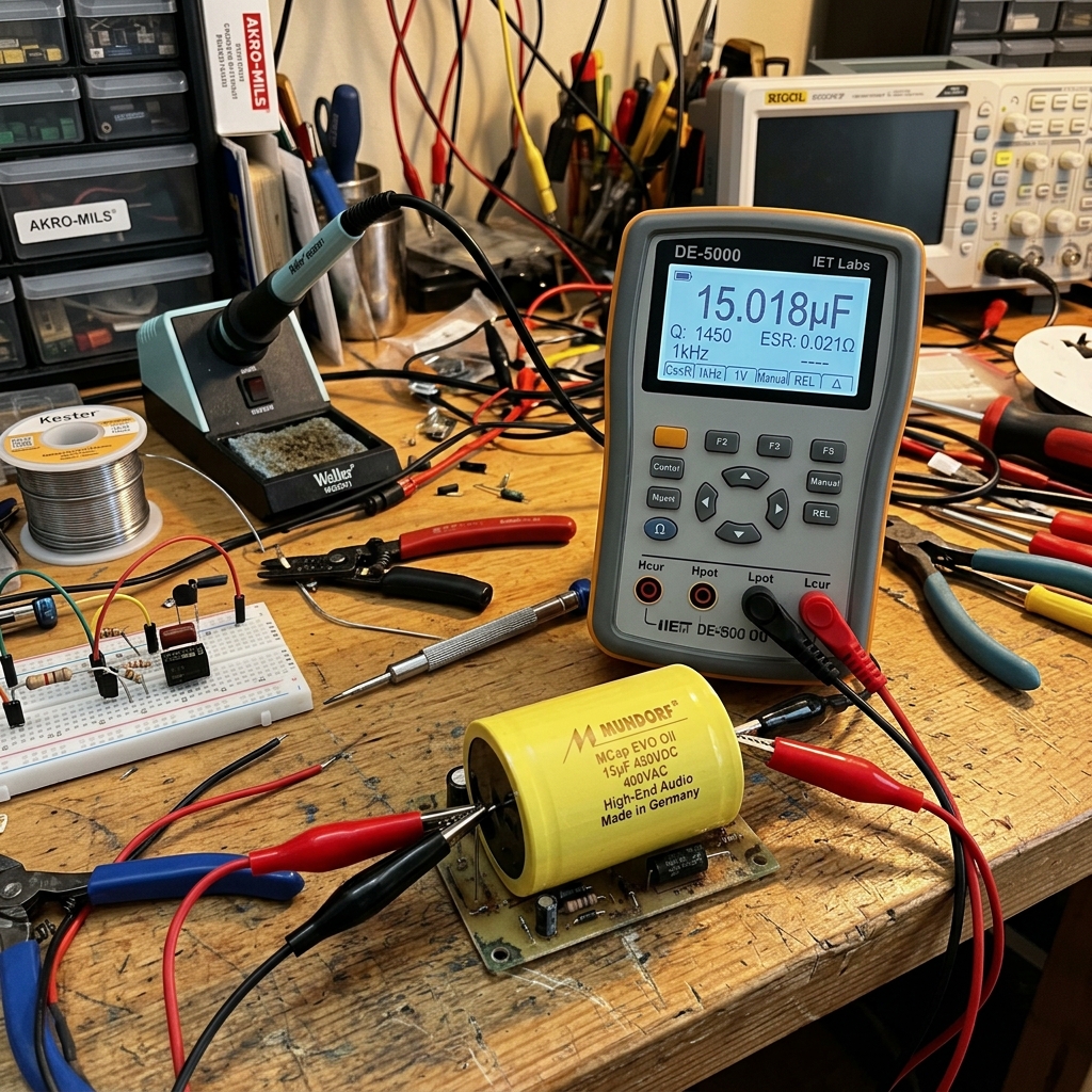
| Ultra-premium (Mundorf MCap EVO Oil) | Oil-impregnated, ultra-low self-inductance | High-end tweeter filter |
What do ESR and self-inductance mean?
ESR (Equivalent Series Resistance) is the deviation from an ideal capacitor—the internal resistance built into the capacitor. Low ESR = less energy loss, less heat generation, and more accurate filter response. Self-inductance (ESL) is an inductive component that deviates from the behavior of an ideal capacitor—at very high frequencies, this also causes distortion. In premium capacitors, both values are minimized.
Tolerance and Measurement-Controlled Selection
The deviation from a capacitor’s nominal value (tolerance) has a significant impact on the crossover’s actual cutoff frequency. Standard tolerance: ±5–10%. For premium products: ±1–2%.
For example, if a 6.8 µF capacitor actually measures 7.3 µF, your calculated 3 kHz crossover point will actually be 2.8 kHz—and this matters, especially for tweeters operating in a narrow transition band. That’s why serious audio enthusiasts measure each capacitor individually with an LCR meter and select them in pairs.
The inductor—a compromise between inductance and resistance
The crossover coil acts as a series element in the low-pass branch (blocking high frequencies) and as a parallel shunt element in the high-pass band (discharging low frequencies to ground).
Air-core vs. iron-core coil
Air-core coil: The most accurate solution—no iron core distortion, no saturation. Disadvantage: Achieving low inductance requires many turns, which increases resistance (DCR).
Ferrite-core coil: Higher inductance can be achieved in a smaller physical size, but the ferrite core becomes a measurable factor (especially at higher signal levels). It is typically used in the low-pass branch at values above 1 mH: at low frequencies, the speaker’s own mechanical/electrical distortion is typically greater than that resulting from the coil’s magnetization, and furthermore, the high-frequency components do not reach the woofer anyway due to the filter—there, the “coloration” from the iron core in the voice coil is less dominant in practice.
Laminated steel core (I-core): A better solution than a solid iron core—the lamination reduces eddy current losses. Premium design: Jantzen’s laminated voice coils.
DCR—The Issue of DC Resistance
DCR (DC Resistance), the ohmic resistance of the coil wire, is present in every coil design. This resistance causes sound pressure loss and distortion of the impedance curve—especially in the low-pass branch, where coils with higher inductance (and thus higher resistance) are used.
A 3 mH ironless coil made with standard 0.8 mm wire can easily reach a DCR value of 0.8–1.2 Ω. On an 8 Ω speaker, this results in a sound pressure loss of 1–1.5 dB and also alters the filter’s Q-factor.
Solutions:
- Thicker wire (1.2–1.4 mm): Larger copper cross-sectional area = lower DCR, but a larger, heavier coil
- Mundorf M-Coil and similar premium ironless coils: Optimized geometry and wire gauge, low DCR
- Silver / OCC wire coils: expensive; silver conducts only about 6% better than copper; DCR is primarily determined by the wire’s cross-sectional area and length
Internal conductor material: OFC, OCC, and silver wire
The conductivity of OFC (oxygen-free copper) is only about 1% better than that of standard electrical copper; OCC (Ohno continuous casting) is long-grain copper; and silver conducts about 6% better. These differences are small relative to the wire’s cross-sectional area in terms of the coil’s DCR; no audible benefit was confirmed in controlled (blind) tests. The measurable factors for a coil are inductance tolerance and DCR—for details, see our article on OFC vs. silver-plated copper coils.
Resistance—which many people overlook
In the crossover, resistors serve the roles of impedance matching, L-pad level matching, and the Zobel network. Although a resistor is often “just” a passive component, the choice still matters.
Resistor Classes in Crossover Networks
Metal-oxide (MOX) and cement-encapsulated (ceramic) power resistors: the most common resistors used in passive crossovers. The inductance of the wound ceramic type is a few µH, which is usually negligible at audio frequencies; what matters is adequate power rating (5–10 W) and tolerance.
Metal-film resistors: A better solution—low thermal noise, low inductance, tight tolerance (±0.5–1%). Recommended for low-power applications; the typical power rating of a metal-film resistor is 0.25–2 W, so the power must be verified when used in an L-pad or series branch.
Non-inductive wirewound resistors: For higher-power applications (L-pad, bypass)—these can handle several watts, and their inductance is minimal due to their special winding.
Premium resistors (e.g., Mundorf MResist, Duelund CAST): tight tolerance and low inductance. However, controlled (blind) comparisons have not confirmed that they offer any audible difference compared to a well-sized metal or metal-oxide resistor—the price primarily reflects construction quality and tolerance.
Measuring Instruments — What You Should Get
Design work can start on paper with simulation (VituixCAD, XSim, LspCAD), but measuring the actual audio circuit requires instruments.
LCR meter — for selecting capacitors and inductors
An LCR meter (inductance-capacitance-resistance) accurately measures the capacitance of capacitors, the inductance of inductors, and the ESR/DCR values of both. This is the first and most important measuring instrument for building crossovers.
Recommended entry-level models:
- DER EE DE-5000: An affordable LCR meter widely used in DIY audiophile circles, with a measurement frequency range of 100 Hz–100 kHz and a basic accuracy of ±0.25%. It is the best value for money in this category.
- MEDE-5011 / MASTECH MS5308: Simpler, less expensive alternatives, but with a narrower measurement range.
- Keysight E4980A / Hioki IM3536: Laboratory-grade models, ideal when accuracy is a priority.
Impedance Meter — for testing speaker and crossover systems
As we mentioned in the previous article about DATS v3: it’s also worth measuring the impedance curve of the entire crossover and speaker system on the finished speaker. If it differs from the simulation, this indicates a discrepancy between the measured and nominal values of the components—and this can be corrected in the simulation.
Microphone-based measurement system—for checking the full frequency response
The true performance of the crossover can only be measured in terms of sound level. This requires:
- Measurement microphone: The UMIK-1 (miniDSP) is the most widely used entry-level option—USB-connected, with a built-in ADC, and factory-calibrated. A more advanced solution: Behringer ECM8000 + external preamp.
- REW (Room EQ Wizard): Free software compatible with Windows, Mac, and Linux that uses the measurement microphone and sound card to measure frequency responses, impulse responses, phase characteristics, and waterfall plots.
- VituixCAD: Not just a design tool, but also software for importing measurement data and optimizing crossovers—by importing the measured frequency responses of individual speakers, it optimizes crossover settings for accurate sound integration.
The measurement chain works as follows: amplifier → speaker → microphone → sound card → REW. It’s a good idea to load the microphone’s calibration file (which can be downloaded for the UMIK-1 from the manufacturer’s website) into the measurement software so that the microphone’s own frequency response doesn’t distort the results.
Sound card — loopback calibration (REW): The output-to-input path (DAC/ADC, or external sound card) should be calibrated in REW using a loopback measurement (feeding the output back to the input or a reference channel); otherwise, the card’s roll-off or ripple will be introduced into the measured speaker response. With cheaper cards, this can cause particularly significant deviations; in the case of the UMIK-1’s built-in ADC, microphone calibration covers the microphone plus its own preamp path; the playback (output) side of the card should be handled separately via loopback if you’re routing the signal through it.
Oscilloscope — for advanced diagnostics
It is not mandatory for audio crossover testing, but an oscilloscope can be used to perform transient/square-wave tests: the square-wave response clearly shows overshoot, asymmetry, and smoothed edges—a quick visual check. For a quantitative assessment of phase linearity, the impulse response and group delay curve (e.g., in REW) are more suitable; the square wave cannot replace these if you want to make a decision about the phase response.
How is a professional crossover design process structured?
The process followed by professional designers isn’t simply “plugging numbers into a calculator and calling it a day”:
Step 1 — Speaker measurement in a free field: Place each speaker on a measurement stand (not on a wall or in a box), and measure frequency response, impedance, and phase data using a semicircular free-field approximation.
Step 2 — Simulation design (VituixCAD): We import the measured data and design the crossover. The simulator displays the combined frequency response, phase response, and sound pressure summation in the transition band.
Step 3 — Prototype Construction: We implement the calculated values using actual components—but not immediately with the final premium components, rather with measured, selected standard parts.
Step 4 — In-situ measurement and iteration: We measure again with the finished enclosure in a real listening position (or at least 1 meter away along the speaker’s axis) and correct any deviations from the simulation.
Step 5 — Final component replacement: Once the values are stable, we replace the prototype components with the final, premium-quality parts. Of course, the values must match exactly—which is why sorting (using an LCR meter) is essential.
Summary
The crossover is not a minor component in a speaker system—it is often the most critical point, where the cheapest decisions can have the most expensive consequences. Key takeaways:
- Capacitors: High/midrange section: film (PP, etc.); low-frequency section (high µF): bipolar electrolytic capacitors are often a good compromise (ESR vs. coil DCR). Do not use polarized electrolytic capacitors in filters. Tolerance and ESR: measure and select accordingly.
- Inductors: DCR is the enemy. Thicker wire, better geometry, and always measure actual inductance.
- Resistors: Choose a type with tight tolerances and a power rating appropriate for the load (MOX, cement-encapsulated, or non-inductive wound); use metal-film resistors for low power applications.
- Measuring Instruments: The combination of an LCR meter (DE-5000) and a REW+UMIK-1 microphone is the minimum entry-level setup; VituixCAD integrates these.
A speaker you’ve built from high-quality components through measurement-based iteration is in a completely different league from one you’ve assembled based on what “seems good.” The two results differ both audibly and measurably.