


Explanation of Speaker Specifications — What Every DIY Builder Needs to Know
If you’ve ever looked at a speaker’s spec sheet, you’ve surely come across an endless string of numbers and letters: Fs = 32 Hz, Qts = 0.38, Vas = 48 liters, Xmax = 9 mm, BL = 11.2 T·m. These aren’t random numbers—each one precisely describes how the speaker behaves, what it’s suitable for, and what kind of enclosure you should build it in. If you don’t understand these, buying parts is a gamble. If you do understand them, then speaker design becomes a predictable engineering task.
This article speaks to you on two levels: if you’re just getting started with the topic, the introductory sections will be easy to understand; if you’re an advanced enthusiast, the technical details and relationships may still offer you new insights.
Why are these parameters important at all?
A loudspeaker is a mechanical-electrical-acoustic system. Just as a car engine has specifications—displacement, torque, compression ratio—a loudspeaker also has its own “soul,” which is described by the Thiele–Small parameters. The foundations were laid by the work of Albert Neville Thiele (1961, republished in the AES in 1971) and Richard H. Small (1972–73), and they have since become the industry standard.
The Thiele–Small parameters (T/S parameters for short) are not merely manufacturer specifications—simulation software (WinISD, VituixCAD, BassBox) relies on them for enclosure design. This is precisely why it matters where you get your parameters from: there is sometimes a significant difference between the manufacturer’s data sheet and reality, which is why serious buyers always work from their own measurements.
Basic Parameters — In Detail
Fs — free-air resonance frequency
Fs (Free-air resonance) refers to the frequency at which the speaker’s diaphragm-voice coil-suspension system resonates freely, without an enclosure. Think of it as the natural resonant frequency of a spring: if you give it a push, it will vibrate most effectively at this frequency.
Typical values:
- Woofers: 20–60 Hz
- Mid-woofers: 35–80 Hz
- Midrange drivers: 150–400 Hz
- Tweeters: 500–2000 Hz
Why is this important? Basic rule: In a sealed enclosure, a speaker’s effective operating range generally begins above Fs (in a bass-reflex system, the −3 dB point may fall below Fs). It makes no sense to push a subwoofer with an Fs of 35 Hz down to 25 Hz in a sealed enclosure—distortion increases, and you’ll reach Xmax before achieving any meaningful sound pressure.
Qts, Qes, Qms—damping factors
These three parameters together describe how “loose” or “tight” the system is at the resonance frequency. In mathematical terms, they are quality factors (Q = quality factor), where a higher number indicates less damping.
Qms (mechanical Q): damping caused by mechanical losses (spring, internal friction). Typically ranges from 2 to 10. High Qms = low mechanical loss = “flexible” diaphragm.
Qes (electrical Q): damping caused by the electromagnetic braking force generated by the voice coil and the magnet. The stronger the magnet and the lower the impedance, the lower the Qes.
Qts (total Q): the combination of the previous two; the formula is: Qts = (Qms × Qes) / (Qms + Qes)
Qts is the parameter you use directly in enclosure calculations:
| Qts value | Quick guideline (heuristic) |
|---|---|
| < 0.30 | A bass reflex or horn is the typical choice; in an open baffle, only with strong active EQ |
| 0.30–0.40 | Both bass reflex and sealed enclosures are viable—simulation will determine the choice |
| 0.40–0.50 | Sealed enclosures are common; bass reflex is still possible |
| 0.50–0.70 | Sealed enclosure (typically with larger volume) or open baffle/dipole — tuning the reflex system is often sensitive |
| > 0.70 | Typically closed or open-back (OB); bass reflex is rarely the first choice (details in the bass reflex article) |
This is, of course, a simplification—the Qts–Vas–Fs triangle collectively determines the ideal enclosure characteristics, but Qts is one of the best quick filters for assessing applicability.
Regarding isobaric configurations: this is not a Qts-based “enclosure type.” Its purpose is to use two subwoofers connected to each other so that the effective Vas is roughly half, thereby achieving the same speaker-level model even in a smaller enclosure—a decision based on size and compromise, not the “counterpart” to high Qts. The passive radiator also has a separate topology (mass + spring) and does not replace the logic of the Qts bands described above.
Vas — Equivalent Air Volume
Vas (Equivalent Compliance Volume) represents the volume of air that exhibits the same elastic (compressible) behavior as the suspension system of the speaker’s diaphragm. It is expressed in liters or cubic meters.
Simply put: if a speaker has an ECV of 50 liters, then its diaphragm is as “soft” as the air inside a 50-liter sealed box. This has a direct impact on the required enclosure volume.
Relationship with Fs and diaphragm size: Large Sd (active diaphragm area) and soft suspension → high Vas. Small Sd, stiff suspension → low Vas. This is why the Vas values of speakers of the same size but designed for different purposes can differ by as much as a 10:1 ratio.
Practical implication: The closed-box volume is not determined solely by the Vas multiplier—even with the same Vas value, completely different volumes are required, for example, for Qts = 0.25 and Qts = 0.5, if you want the same target closed-box Q value (Qtc, e.g., Butterworth 0.707). The classic relationship: Vb = Vas / ((Qtc/Qts)² − 1) (in liters, if Vas is also in liters). “Vas × 0.3–1.0” is only a very rough order of magnitude that omits complex factors; the final volume always results from the combination of Qts, Vas, and the chosen Qtc—hence the simulator. For bass reflex systems, the optimum can be calculated using a different formula.
Xmax — maximum linear excursion
Xmax (Maximum linear excursion) represents the most important sound pressure limit: it is the value, expressed in mm, by which the diaphragm can move linearly in both directions without the uniformity of the magnetic field being disrupted. If you exceed Xmax, distortion increases exponentially.
More precisely, from a technical standpoint: Xmax generally denotes the point at which the BL factor (force factor) decreases by 10% relative to the baseline. Some manufacturers use 15% or 20%—it’s worth checking what the datasheet is based on.
Another common definition (geometric): on many spec sheets, Xmax ≈ (active coil height − air gap height) / 2. This can yield a value significantly different from the definition based on BL reduction for the same speaker; when purchasing or comparing products, it’s worth knowing which method the manufacturer uses.
Relationship between sound pressure and Xmax (at low frequencies):
At low frequencies, sound pressure is determined by three factors: Sd (active diaphragm area), Xmax, and the frequency itself. The relationship is as follows: the lower the frequency, the greater the excursion required to achieve the same sound pressure level. This explains why subwoofers require an Xmax of 15–30 mm, while 4–8 mm is sufficient for a mid-bass driver.
BL — Force Factor (Motor Force)
BL (Force Factor) is the “force” of the magnet system—more precisely, the product of the active length of the voice coil (L) and the magnetic flux density (B). Its unit of measurement is the tesla-meter (T·m).
The higher the BL, the more effectively the electrical circuit can dampen mechanical motion—this reduces Qes and generally improves controllability. In modern premium subwoofers, the BL value ranges from 10 to 20 T·m; in subwoofers, it can even reach 25–30 T·m.
Important relationship: BL² / Re = effective electrical damping of the motor force. This is the basis of the so-called “Electrical Damping Factor.” Higher BL and lower Re = stronger electrical damping = tighter bass.
Re — DC Coil Resistance
Re (DC Resistance) is the direct-current resistance of the speaker voice coil. This is not the same as the nominal impedance (which is 4 Ω, 8 Ω, etc.)—impedance is frequency-dependent, while Re is a direct-current measurement.
Typically: Re ≈ 0.6–0.85 × nominal impedance. For an 8 Ω speaker, Re is usually around 5.5–7 Ω.
Why is this important when designing a crossover? The filter elements of the crossover also respond to the Re value—especially in resistive load compensation (Zobel network). If you ignore Re, the filter’s actual crossover point will differ from the designed one.
Le — Voice Coil Inductance
Le (Voice Coil Inductance) is the measured inductance of the voice coil (in mH). Some manufacturers specify this value at 1 kHz, others at 10 kHz, or use a frequency-dependent model (e.g., the Leach or Wright approach), because near 1 kHz, due to resonance and the influence of mechanical components, a single measurement point is less representative of high-frequency behavior. Always check the measurement frequency or model in the datasheet. It is this inductance that causes the rise in impedance observed at high frequencies, which is one of the most vexing problems in crossover design.
For speakers with high Le, the use of a Zobel network is almost mandatory: a series R–C circuit connected in parallel to the speaker complements and linearizes the impedance characteristic. Omitting this causes the crossover’s actual operation to deviate from the simulation.
Complex Parameters and Efficiency
SPL efficiency (1W/1m)
The efficiency specified in the catalog in dB (e.g., 89 dB / 1W / 1m) indicates the sound pressure level measured at a distance of 1 meter with 1 watt of input power. This is a logarithmic scale: a 3 dB increase corresponds to a doubling of power (a barely audible difference), whereas approximately 10 dB is required to double the perceived volume.
Practical implication: A speaker with an efficiency of 86 dB requires twice as much power to produce the same volume as one with an efficiency of 89 dB. The 6 dB difference means four times the power requirement.
EBP — Efficiency Bandwidth Product
The EBP (Efficiency Bandwidth Product) is a simple heuristic for quickly assessing enclosure suitability: EBP = Fs / Qes.
| EBP value | Recommended box shape |
|---|---|
| < 50 | Closed box |
| 50–100 | Transitional (both are possible) |
| > 100 | Bass reflex |
This is not a substitute for simulation, but it’s a good first filter. It’s particularly important in the 50–100 range: the table doesn’t clearly indicate whether to choose reflex or sealed—there, Qts, Vas, Fs, and the desired −3 dB / sound character all play a role; it’s worth running both options through the software.
Why measure it yourself—and with what?
Manufacturer data sheets are sometimes rough estimates, and due to manufacturing tolerances, individual units may deviate from the nominal value. Serious DIYers therefore rely on their own measurements.
The minimum equipment needed for your own measurements:
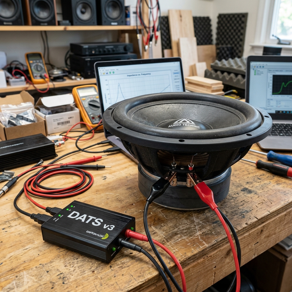
- DATS v3 (Dayton Audio) or a similar USB impedance meter—this is the cheapest reliable entry-level option; it automatically calculates T/S parameters
- REW (Room EQ Wizard)—free software that can also be used for impedance measurement with a compatible sound card
- Holm Impulse or VituixCAD measurement module — for advanced measurement and simulation work
The measurement process in brief: Measure impedance with the speaker suspended in free air (not resting on a surface or inside a box); the software calculates all T/S parameters from the resonance peak and the impedance curve.
A trick well-known in professional circles: the “added mass” method for measuring Vas—you attach a known mass to the center of the diaphragm, measure again, and Vas can be calculated from the frequency shift. Both the added-mass method and the box method using a known volume are accepted; accuracy depends on the care taken during the measurement.
The Relationship Between Parameters and Enclosure Calculations — A Specific Example
Consider a typical SB Acoustics subwoofer: Fs = 30 Hz, Qts = 0.38, Vas = 55 liters, Xmax = 10 mm, BL = 13 T·m.
A Qts of 0.38 is a realistic range for both reflex and sealed enclosures. EBP = Fs/Qes—if Qes = 0.42, then EBP = 30/0.42 ≈ 71, so this falls in the middle of Small’s transitional (50–100) band: it does not automatically follow that “reflex is better”—it’s worth comparing both approaches in WinISD (or another T/S simulator) for the same speaker.
If we choose the bass-reflex variant in this example, optimized tuning could result in a cabinet of approximately 35 liters tuned to 35 Hz—this is one possible optimum, not a mandatory consequence of the table. In a sealed enclosure with the same parameters, the volume would be approximately 25–30 liters, with the −3 dB point around 55–60 Hz and a −12 dB/octave rolloff—a different sound, a different application. The choice between the two is determined by the simulated frequency response curves and the goal (deep bass vs. fast, tight bass).
This line of reasoning isn’t possible as long as the parameters are just numbers—once you understand them, the design becomes logical.
Summary
Speaker parameters are not some secret language used by manufacturers—they are an engineering descriptive system that precisely tells you what kind of enclosure the speaker is suited for, what it is capable of, and what it is not. The most important parameters are: Fs (resonance frequency), Qts (damping factor, enclosure selection), Vas (diaphragm compliance), Xmax (maximum linear excursion), BL (motor force), and SPL efficiency.
If you understand these, you won’t just be able to buy speakers—you’ll be able to design them, too. This is the difference that sets DIY audiophiles apart from those who build randomly assembled enclosures.
Author’s note: The measurement methods and simulation principles described in this article are based on publicly available literature on the Thiele–Small theory and the relevant standards of the AES (Audio Engineering Society).